Braille Height User Guide
This user guide is specific for SMA – Microtek – Contex IQ Flex 3D scanners.
Overview
The GlobalVision Braille Height basic software is designed to detect the presence, translate, and measure dot height on printed packaging components such as cartons and paper. The software uses revolutionary algorithms to extract braille information in order to measure average dot height and dot spacings. The system can also inspect PDF braille vs. the actual braille on printed packaging.
The new Braille Height software version is available as a plug-in and now allows the measurement of individual braille dots and spacing and will generate a secondary report called the "Detailed Braille Inspection Report". This software is compatible with existing GVD software versions in the form of an easy-to-install plug-in. This plug-in uses an advanced calibration for increased accuracy.
This document provides the necessary information and steps required to scan packaging components using the Contex A2 or the Microtek A0 or the SMA A0 scanner with GlobalVision Desktop software.
Please note that only these 3D scanners are compatible.
The SMA Graphics User Guide is located right under this document.
For more information, please consult the Braille Height Training Videos for a quick-start guide and easy-to-follow instructional videos.
Product Specifications
The following table describes the scanner’s specifications:
DESCRIPTION | SPECIFICATIONS |
Sample Type | Cartons, plastic or paper |
Input Voltage | 110-220 V; 50-60 Hz |
Office Environment | Vibration-free table |
Scan DPI | 300 |
Light Source | Dual |
Maximum Size | A2 or A0 |
Scanner | Contex IQ Flex A2, Microtex A0, SMA A0 |
Software |
|
Key Features
Individual dot height measurement
Translate all Braille regions in 43 languages
Multiple braille region inspect dot height and spacing
Pass/Fail per dot & region
Pass/Fail for Spacing (Dots, Cells, Lines)
Multiple repeat Press sheet braille inspection
Compare dot presence to PDF
Translate Braille in over 40 languages
e_signature and lock report
Color-coded dot height for individual threshold
Hardware Overview
Hardware Set-Up
The following steps outline the hardware set-up procedure:
Ensure the GlobalVision scanner is on a secure, level platform with minimal vibration.
Connect the power cord to a power supply that complies with and then to the Power Adapter port on the back of the scanner.
Connect the network cable to the computer port.
Clean the scanner glass surface using approved static-free electronic equipment cleaning products.
Calibrate the scanner as outlined in this guide or visit the Globalvision Help Center.
See Training Videos: https://help.globalvision.co/gvd/braille-help-general-videos
These videos also show basic usage of the Detailed Braille Inspection Plug-in.
Placing the Sample
To place your sample prior to the scanning process:
Ensure all software is installed.
Ensure the scanner is set up.
Ensure the scanner is powered on.
Once the scanner has initialized, lift the scanner lid and place your sample on the glass platten. Push the sample against the top edge to make sure it is straight.
Orientation: Place the sample with the dots face down in the proper reading order. A good way to know is to match the PDF layout.
Note: The Braille software will try to correct for orientation.
Setting the Resolution
The resolution defaults to 300 DPI.
Selecting the Scanner Source
To select your source (scanner) and start scanning:
On the Main toolbar, click on the Scanner icon.

Selecting Scanner Sources for the Braille Plug-In
To use the new Braille plug-in, select one of the following from the Scanner Selection Window:
"Contex Braille" for the IQ Flex A2 scanner
"Microtek Braille" for the Microtek LS4600 A0 scanner
Go to Braille settings > General > Click “Show scanner interface”
Also see section on Invert Lights
“SMA Braille” for the VersaScan 3650 A0 scanner.
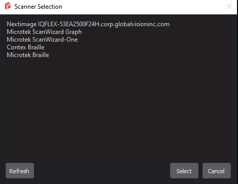
Figure 5
Configuring the Braille Plug-In Module (SMA & Microtek scanners only)
Select the Scanner icon in the Main Toolbar.

Select Scanner Settings from the menu below to open the Braille Settings window.
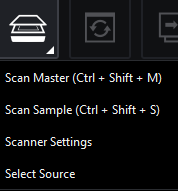
Fig 6
Braille General Settings
Here the basic functions to save scans and reports can be found.
Setting up custom reports and prompts are available.
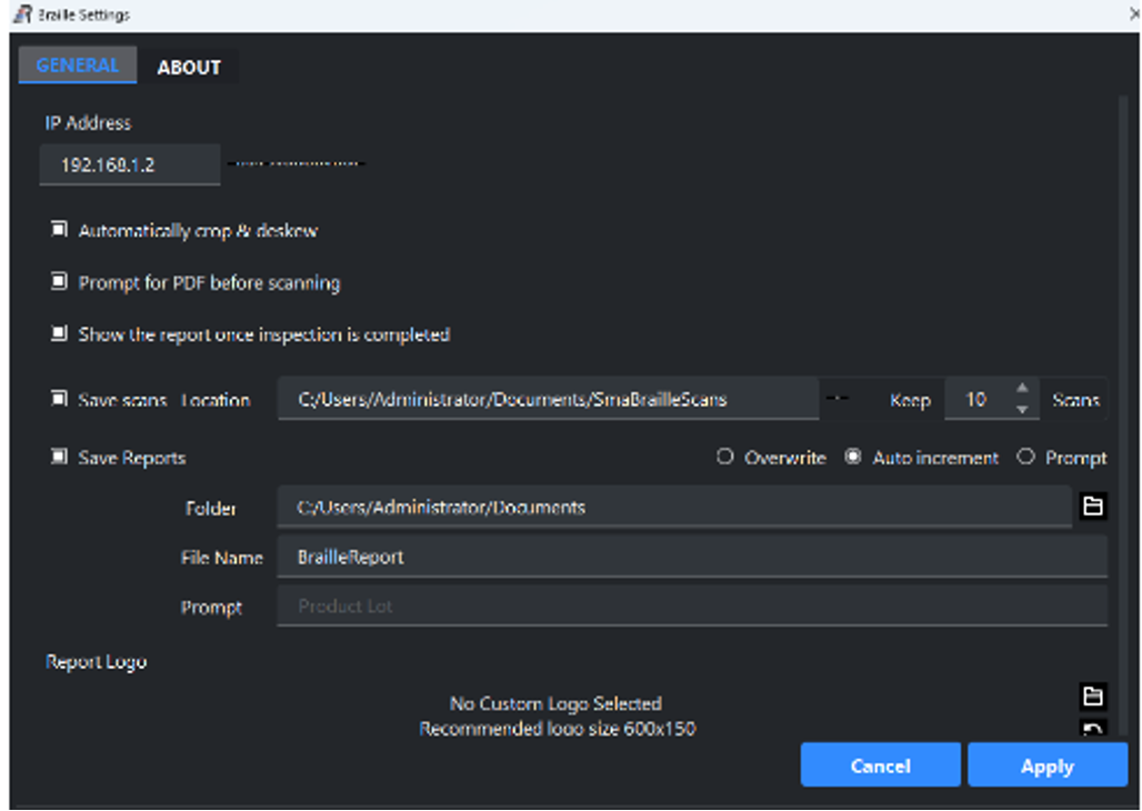
Fig. 7
Check “Prompt for PDF before scanning” (Fig.7) if you require inspection of the braille against a PDF file. This is useful in finding translation errors. It will also highlight any missing or added braille dots.
It is also recommended to Check “Show the Report once inspection comple
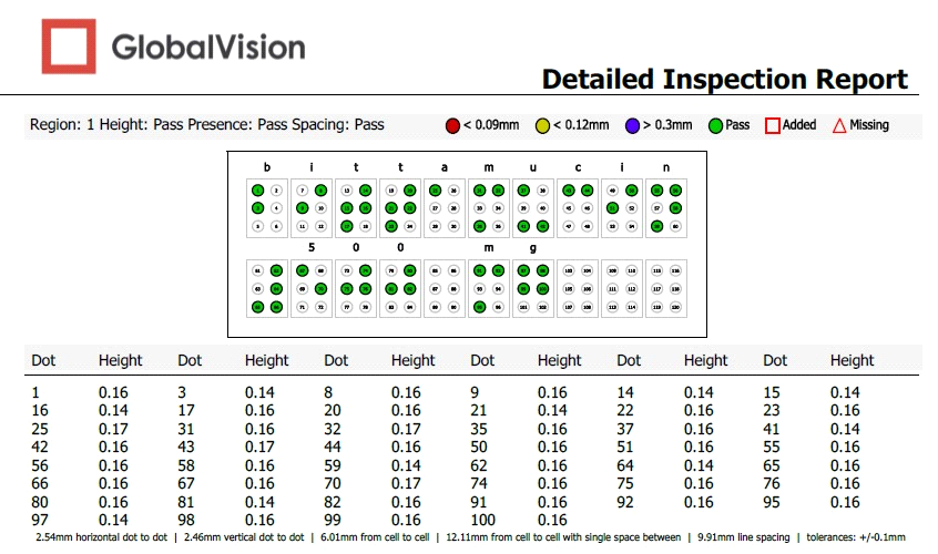
Example report
Fig. 10
There are several ways to save the Braille report.

Fig. 11
There are several ways to save the Braille report.
Overwrite (Fig. 11) will use the Filename -> BrailleReport every time and overwrite it in the Folder selected.
Auto Increment (Fig. 11) will save each instance of the Detailed report and increment the file name -> BrailleReport001.pdf, BrailleReport002.pdf, etc.
Prompt below (Fig. 11 & 12) will allow entering the Product Lot which will be used to create a custom PDF Report filename.
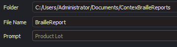
Fig. 12
Adding Company Logo to Reports

Fig. 13
You can add your company logo as shown in Fig.13 to the Detailed Braille Report in this section.
The logo will appear on each page of this report.
About
This tab shown shows the version of the Braille Plug-in that is installed.
Fig.14
How to Run Braille Height Inspection
This section explains how setup and inspect Braille Height.
Click on the “Sample” Scanner icon
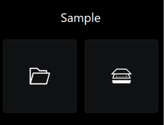
Select the PDF file when prompted (Select Cancel and Yes if there is no PDF)
Select the desired Profile.
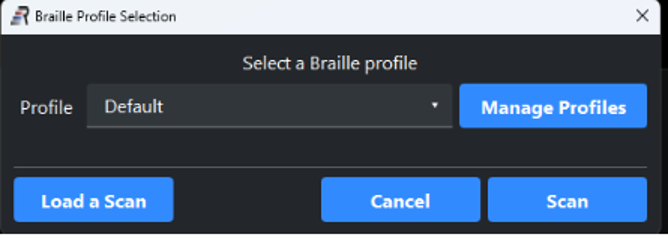
Clicking on Scan will start the scanning process.
Clicking on Load a Scan will permit loading a previously saved scan.
Click on Manage Profiles to configure the Inspection as below
Here you can Add & Import profiles.
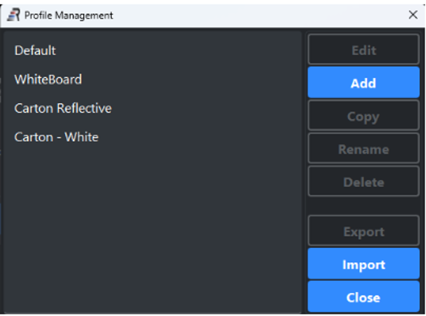
To configure a profile, simply select the desired profile
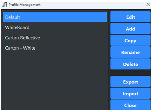
Click Edit
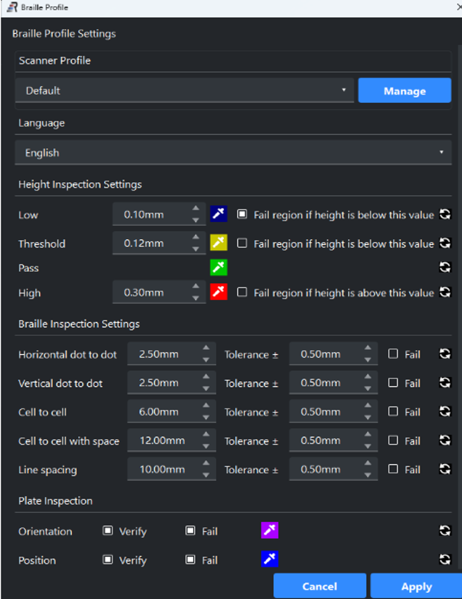
Braille Height Inspection Settings
Clicking on the eyedropper symbol, you can change the dot color of individual braille dots based on their heights. As shown, any dot below 0.10mm will be colored blue. The check box is also selected to fail this region if the condition is met. The same can be done for High dots.
Note that any failed condition will cause the Braille Report to be set to Fail.
Braille Spacing Settings
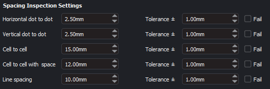
Fig. 9
There are many Braille spacing settings that are available. These include dot-to-dot, Cell-to-Cell, and Line spacing.
If the "Fail" check box is selected, it will allow the Braille report to be set to Fail.
Language
Using the drop-down (Fig. 7), select the language to be used for braille translation.
Braille language can also be selected directly in the GVD main toolbar as shown below:
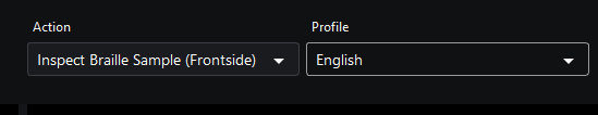
Fig. 8
Advanced (Height Coefficient)
Use this slider (Fig.7) to adjust the Braille dot height coefficient. This coefficient will assist in calibrating the dot heights in each braille region that is detected. This is necessary due to differences in individual scanner lighting. As your scanner ages, perform this adjustment at least once a year. Measure actual dot height using a micrometer and verify against the mean dot height. Adjust the coefficient value accordingly.
Light Angle
This function is for SMA scanners only.
The light angle is adjustable from 50-400.
Default Light angle is 175.
Braille cartons with primarily white backgrounds, Light Angle = 150
Braille cartons with reflective of dark backgrounds, Light Angle = 250
Dot Enhancing
This feature is useful when there is no barcode and/or artwork on the carton being inspected.
Increasing this value will dilate (increase) the braille dot shadow. Decreasing this value will erode (decrease) the braille dot shadow.
Default value is 0.
For White Braille cartons with no artwork, set value to 6.
For White Braille Press sheets with no artwork, set value to 8.
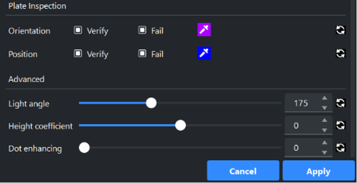
Plate Inspection
Activating Orientation with check for Flipped braille regions.
Activating Position will check for wrong braille region location.
(These two functions apply only to Press sheets)
Appendices
Appendix 1: Braille Plug-in Installation
The following steps outline the installation process for the GlobalVision Braille Plug-in installer software:
Ensure your GlobalVision Desktop software is already installed.
Ensure the scanner is powered off and the USB adapter is not plugged into the computer.
Right-click on the GlobalVision installer and select “Run as administrator”.
The welcome Setup – GlobalVision screen displays.
Follow the steps.
Appendix 2: How to Calibrate the Contex A2 Scanner
The Contex A2 scanner must be calibrated prior to use.
Clean the glass plate on the scanner.
Place the Contex calibration sheet in the scanner.
Ensure that the Whitepoint value is 295 and Blackpoint is 0.
Select "General" from the Braille Settings Task Bar (Fig.15)
Click "Perform scanner calibration" (Fig.15)
Click OK then SAVE
Note: also reference the GlobalVision Help Center Training videos on how to Calibrate.
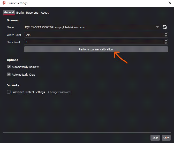
Fig.15 Contex A2 Braille Calibration
Appendix 3: How to Configure the Microtek A0
The Microtek A0 scanner must be configured prior to use.
Clean the glass plate on the scanner.
Make sure the Scanner is UNLOCKED.
Rotate the pin 1/4 turn to release as shown in Fig. 16.
There are 2 pins, one on each side which must be unlocked.
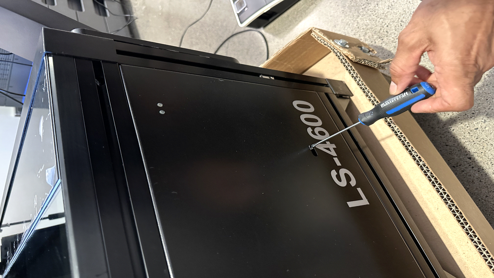
Fig 16.
Open the application Microtek ScanWizard Graph as shown in Fig. 17.
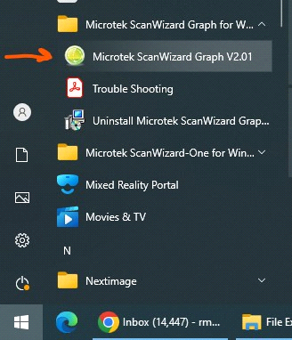
Fig. 17
Select the Settings icon (Gear symbol) as shown in Fig.18.
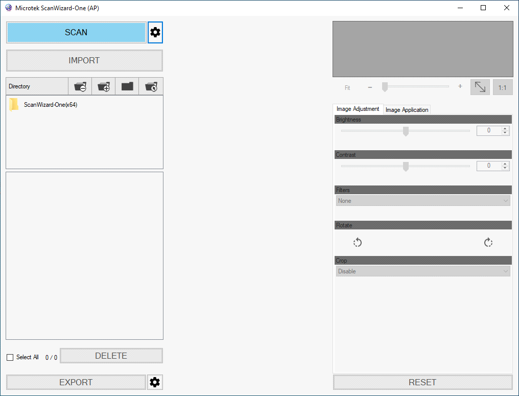
Fig. 18
Expand the Crop region to the maximum scanning area as shown in Fig 19 & 20.
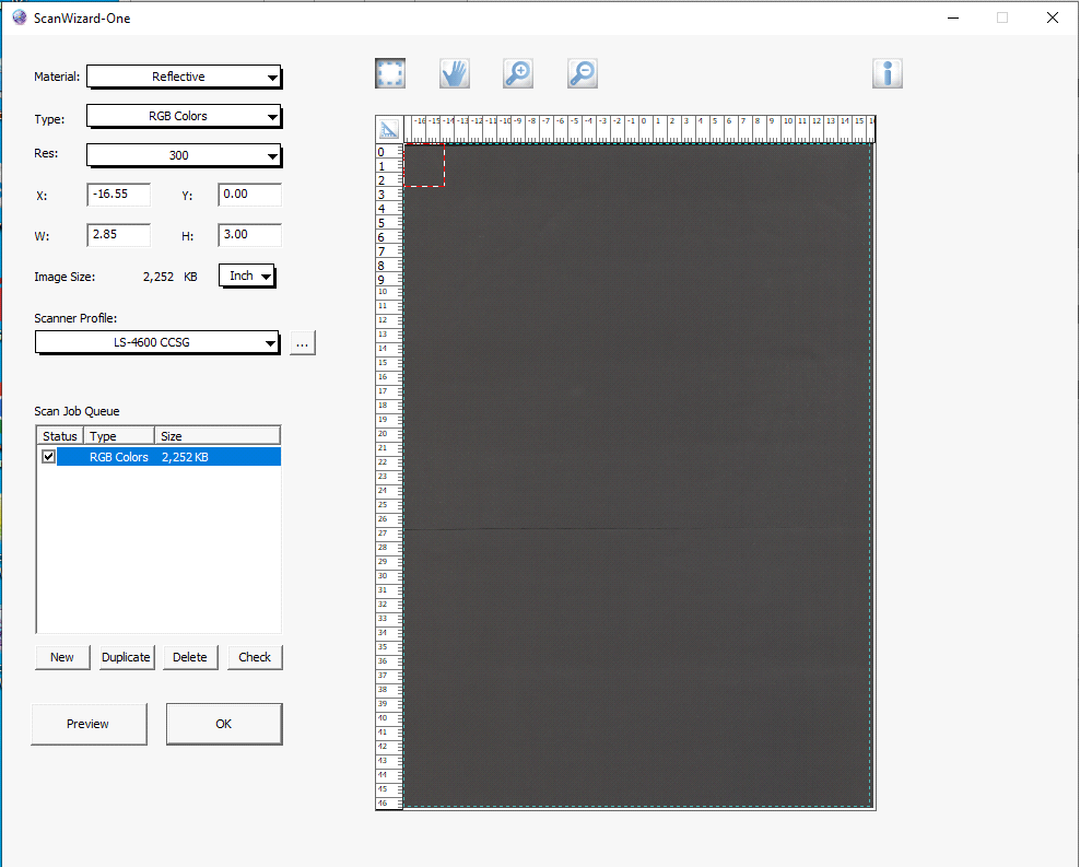
Fig 19
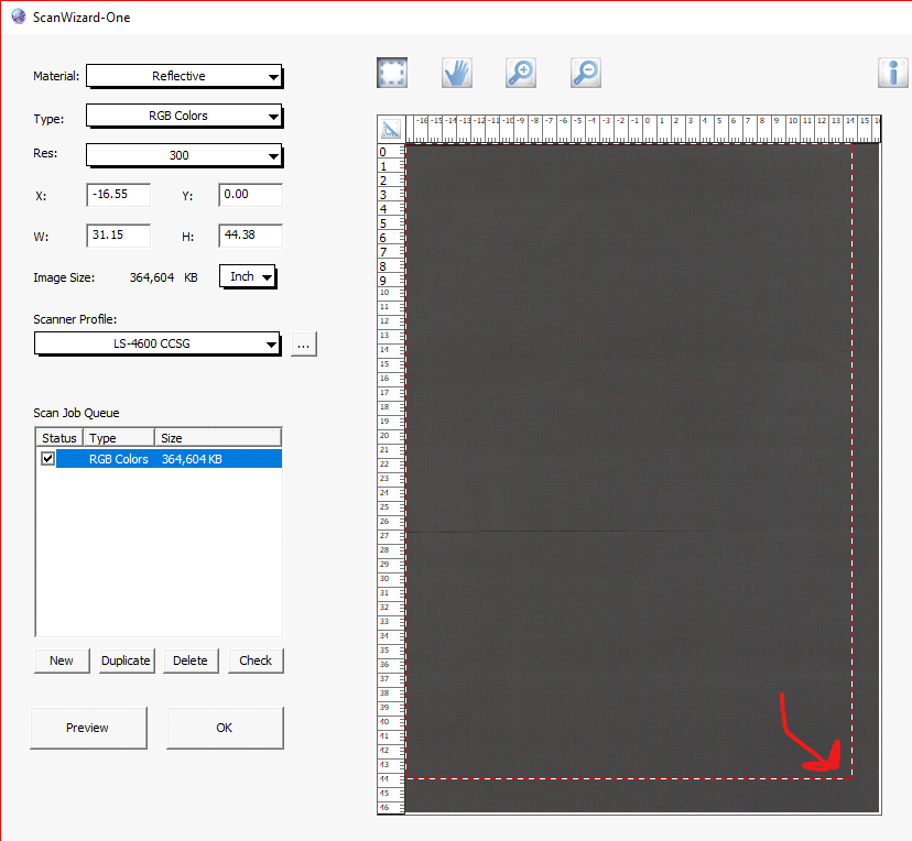
Fig 20
Select Ok.
The scanner is now Configured.
Appendix 4.0: How to Calibrate the Microtek A0 Scanner
The A0 requires a final calibration step.
Place the calibration sheet (Grid Press sheet) in the scanner face down.
Close the lid.
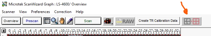
Fig. 21
Make sure the scanner is in calibration mode (Red arrow) as shown in Fig. 21.
Select "Create TR Calibration Data".
Click Next.
Wait for the scanner to calibrate. Approximately 10 minutes.
Close application.
The Scanner is ready.
Please refer to our page for Microtek A0 Braille Installation and Setup for complete calibration instructions in the Scanner Guides and TroubleShooting section.
Appendix 4.1: How to Fix the Camera Stitching on the SMA A0 Scanner
Please refer to our page for the SMA A0 Scanner Calibration and Stitching correction in the Scanner Guides and TroubleShooting section.
Appendix 5: Braille Scanners
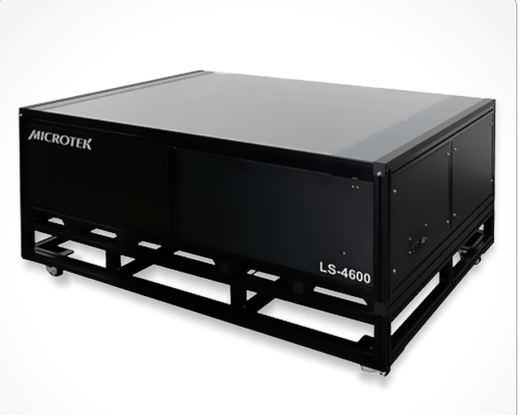
Fig. 22a Microtek A0 Scanner
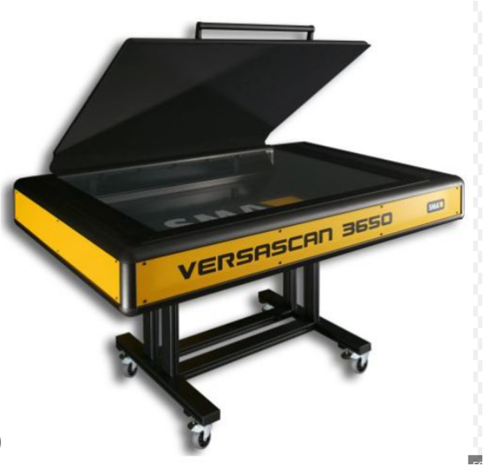
Fig. 22b SMA A0 Scanner
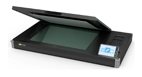
Fig. 22c Contex A2 Scanner
Appendix 6: Example Reports

Fig 23. Single Carton Detailed Braille Report
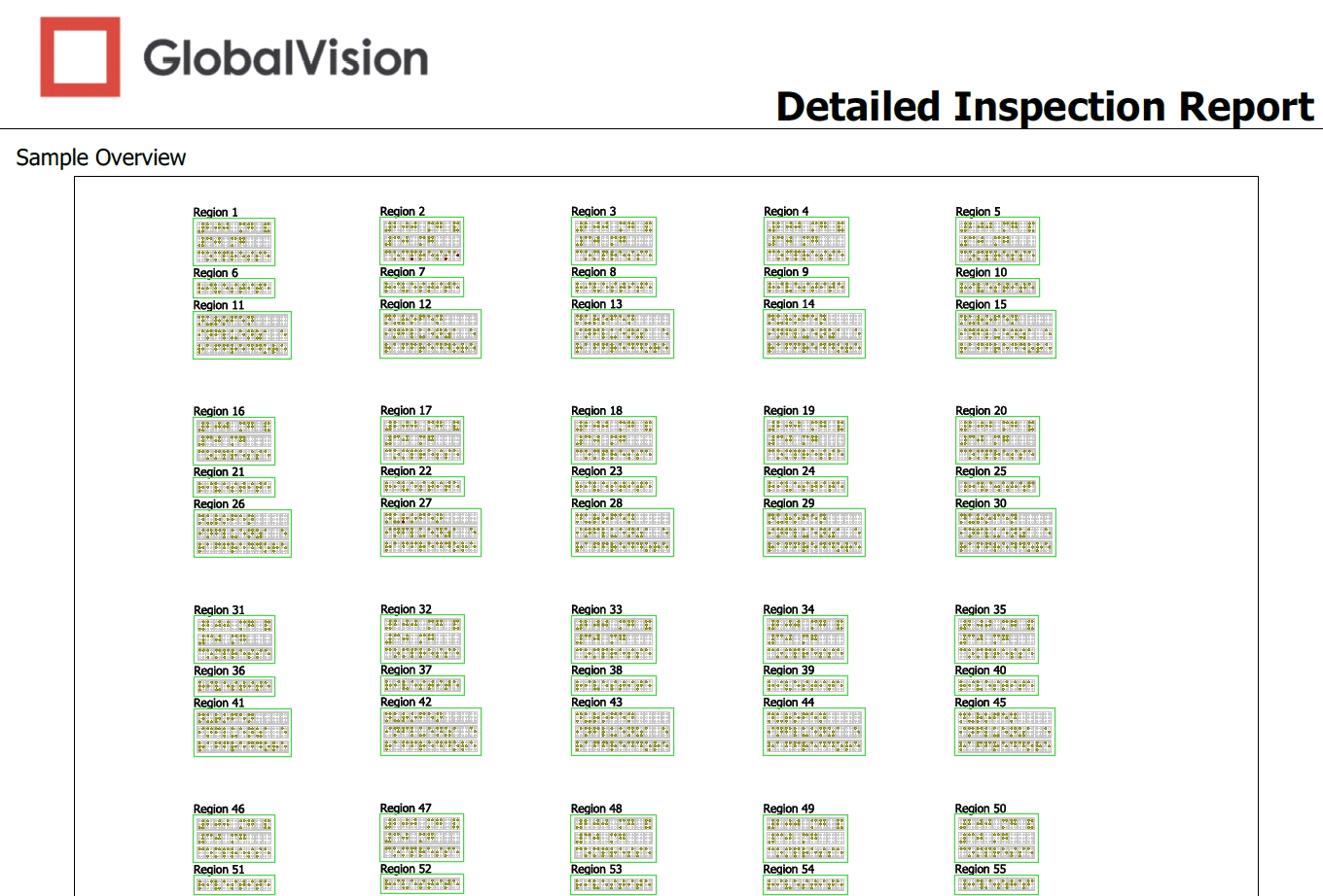
Fig. 24. Multi-Carton / Multi-Region Detailed Braille Report