Flatbed Scanner Table Assembly Guide
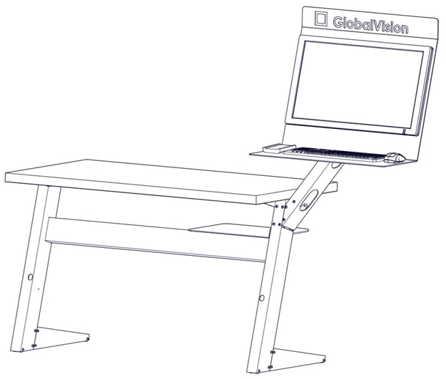
GlobalVision Flatbed Scanner Desktop Inspection System with Monitor Arm
Note: Do not fully tighten any bolts until every part is assembled.
Instructions
The following instructions are to assemble the Flatbed scanner Table:
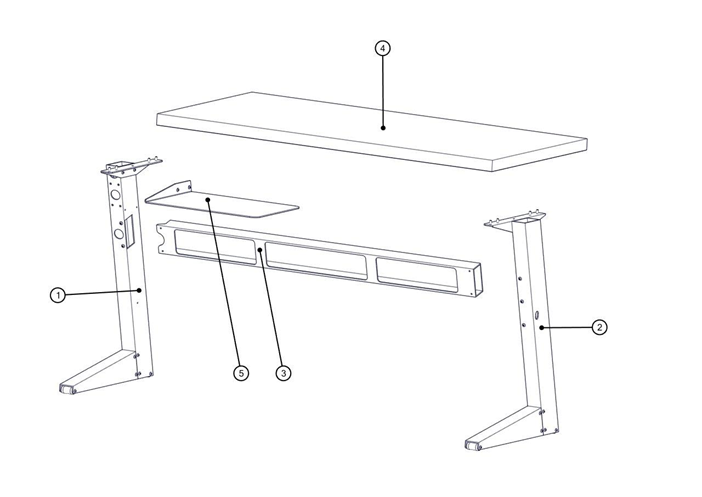
GlobalVision Flatbed Scanner Table Parts Assembly
Assembly Parts List
| 1 | # | Part Name | Quantity |
| 2 | 1 | Right Leg | 1 |
| 3 | 2 | Left Leg | 1 |
| 4 | 3 | Horizontal Support Bar | 1 |
| 5 | 4 | Tabletop | 1 |
| 6 | 5 | Computer Tray | 2 |
| 7 | 6 | Bolts | 14 |
| 8 | 7 | T-Handle Allen key 3/16" | 1 |
GlobalVision Flatbed Scanner Table Parts List
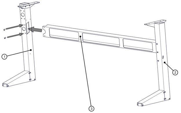
Step 1
Slide the Left Leg (Part #2) in the Horizontal Support Bar (Part #3), for (two) bolt entry points align with one another. Place and fasten the two bolts.
Attaching the Left Leg
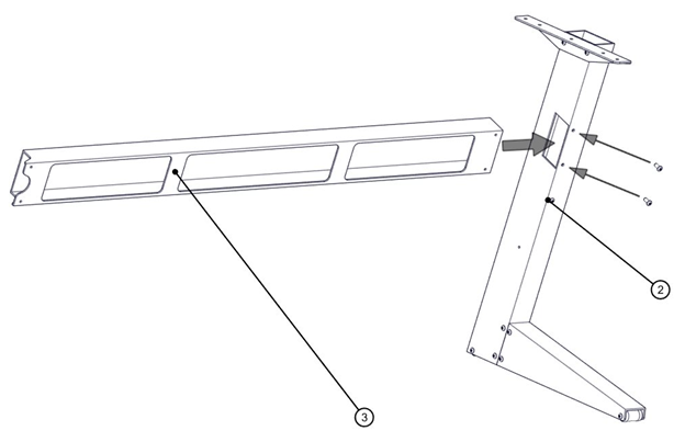
Step 2
Slide the Right Leg (Part #1) in the Horizontal Support Bar (Part #3), for the (two) bolt entry points to align with one another. Place and fasten the two bolts.
Attaching the Right Leg
Step 3
Place the Tabletop (Part #4) on top of the two legs (Parts #1 and #2) by aligning it with the (four) bolt entry points on each side. Place and fasten the four bolts on each side.
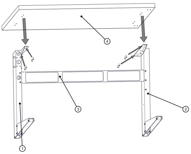
Attaching the Table Top
Step 4
Connect the Computer Tray (Part #5) on the inside of the Right Leg (Part #2) so that its flat surface rests on the Horizontal Support Bar (Part #3) and for the (two) bolt entry points align with another set. Place and fasten the two bolts.
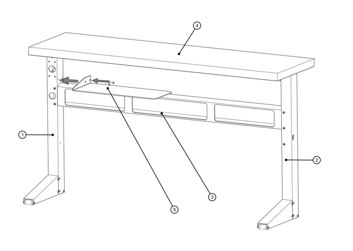
Connecting the Computer Tray
Step 5
Connect the Monitor Arm to the right side of the Right Leg (Part #1).
Note: Follow instructions with the Monitor Arm assembly guide.
Connecting the Monitor Arm
Step 6
Tighten all the bolts to ensure the Flatbed Scanner Table is safe and ready to use.
Assembly Guide PDF:
GlobalVision Flatbed Scanner Table Assembly Guide rev.002.pdf