I-Count Assembly Guide
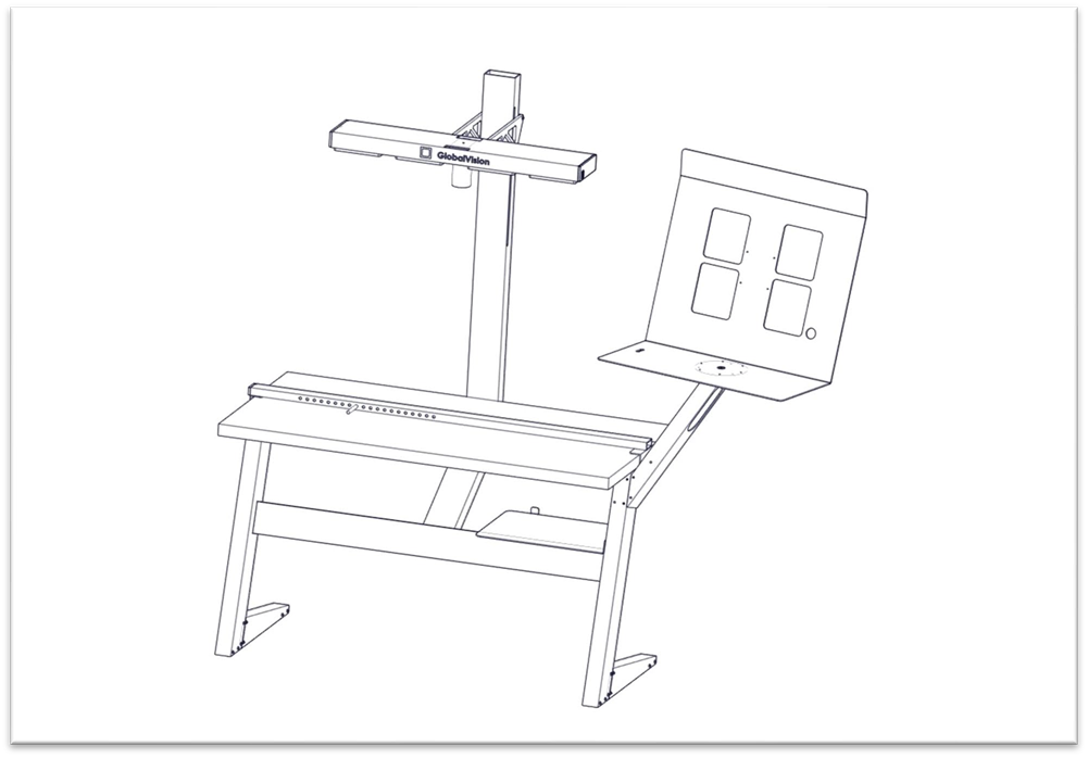
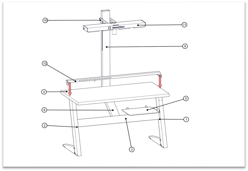
GlobalVision I-Count system with Monitor Arm
Note: Do not fully tighten any bolts until every part is assembled.
Instructions
The following instructions are to assemble the I-Count System:
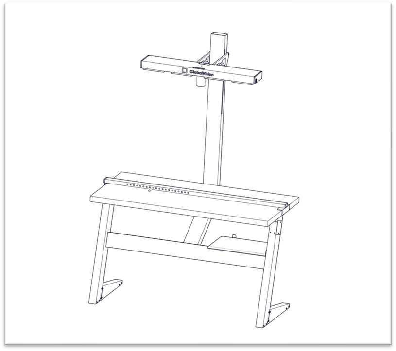
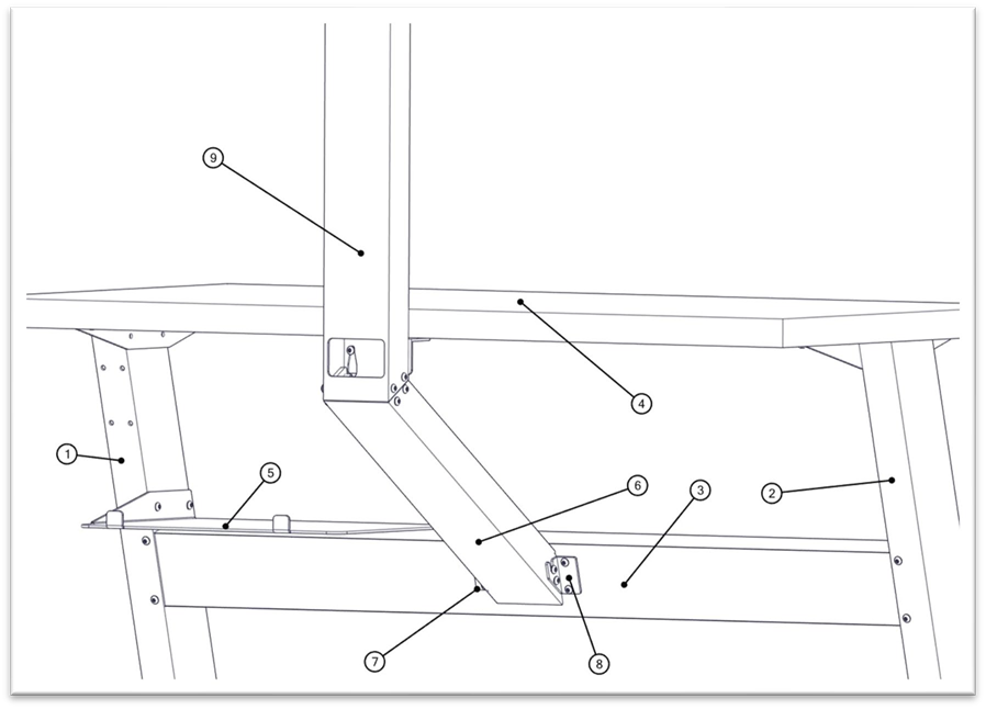
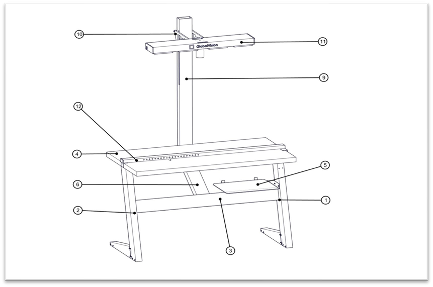
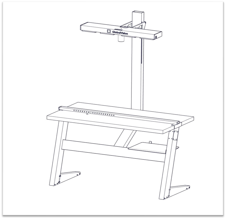
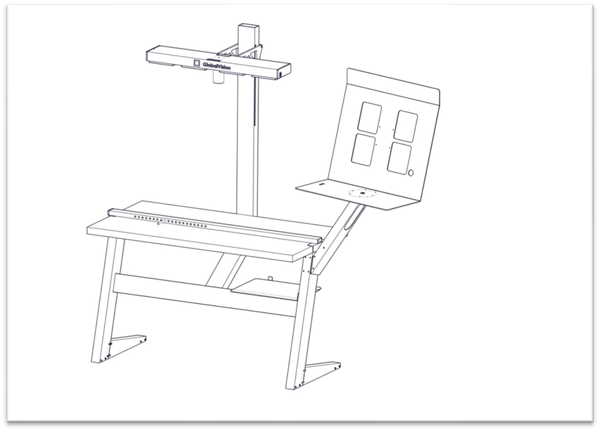
GlobalVision I-Count System without Monitor Arm
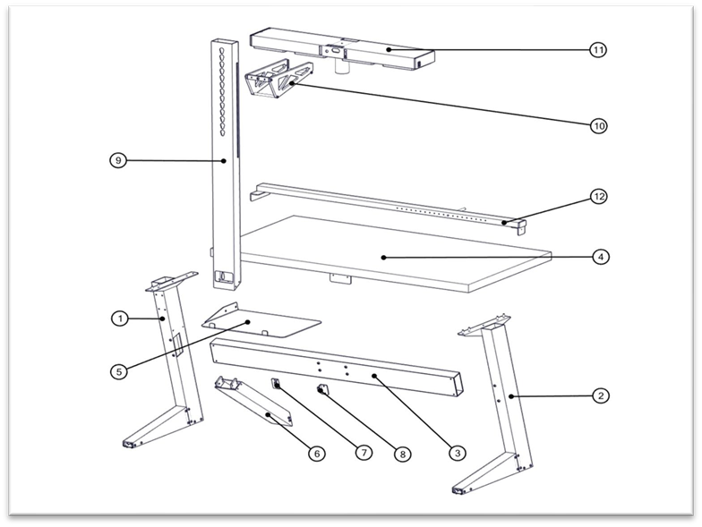
GlobalVision I-Count System Assembly Parts
Parts List | ||
# | Part Name | Quantity |
1 | Right Leg | 1 |
2 | Left Leg | 1 |
3 | Horizontal Support Bar | 1 |
4 | Tabletop | 1 |
5 | Computer Tray | 1 |
6 | Diagonal Column | 1 |
7 | Right Side Mounting Bracket for Diagonal Column | 1 |
8 | Left Side Mounting Bracket for Diagonal Column | 1 |
9 | Main Column | 1 |
10 | Column Head | 1 |
11 | Light/Camera Fixture | 1 |
12 | Tray Support | 1 |
13 | Bolts | 28 |
14 | T-Handle Allen key 3/16" | 1 |
GlobalVision I-Count System Parts List
Step 1
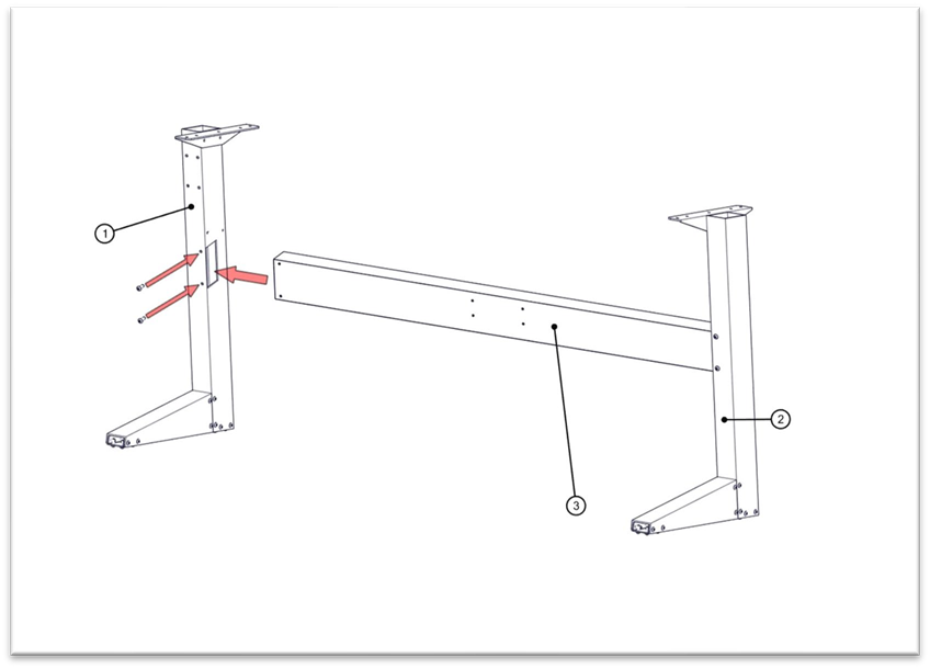
Slide the Left Leg (Ref Table 1: Part #2) in the Horizontal Support Bar (Ref Table 1: Part #3), so that the (two) bolt entry points align with one another. Place and fasten the two bolts.
Attaching left leg with horizontal support bar
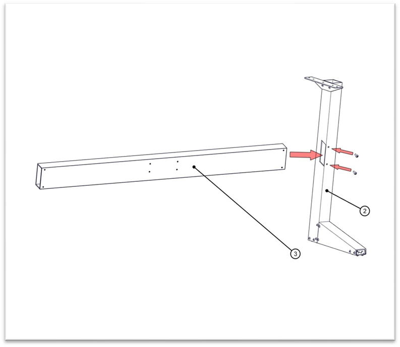
Step 2
Slide the Right Leg (Part #1) in the Horizontal Support Bar (Part #3), so that the (two) bolt entry points align with one another. Place and fasten the two bolts.
Attaching right leg with horizontal support bar
Step 3
Place the Tabletop (Part #4) on top of the two legs (Parts #1 and #2) by aligning it with the (four) bolt entry points on each side. Place and fasten the four bolts on each side.
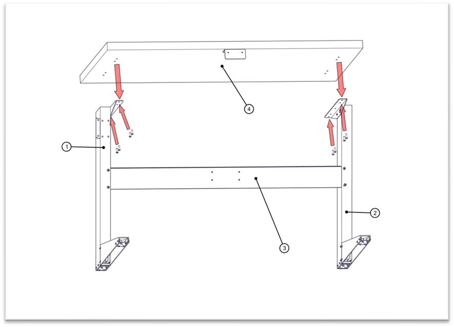
Attaching the Tabletop on the two legs
Step 4
Connect the Computer Tray (Part #5) on the inside of the Right Leg (Part #2) so that its flat surface rests on the Horizontal Support Bar (Part #3) and the (two) bolt entry points align with the other set. Place and fasten the two bolts.
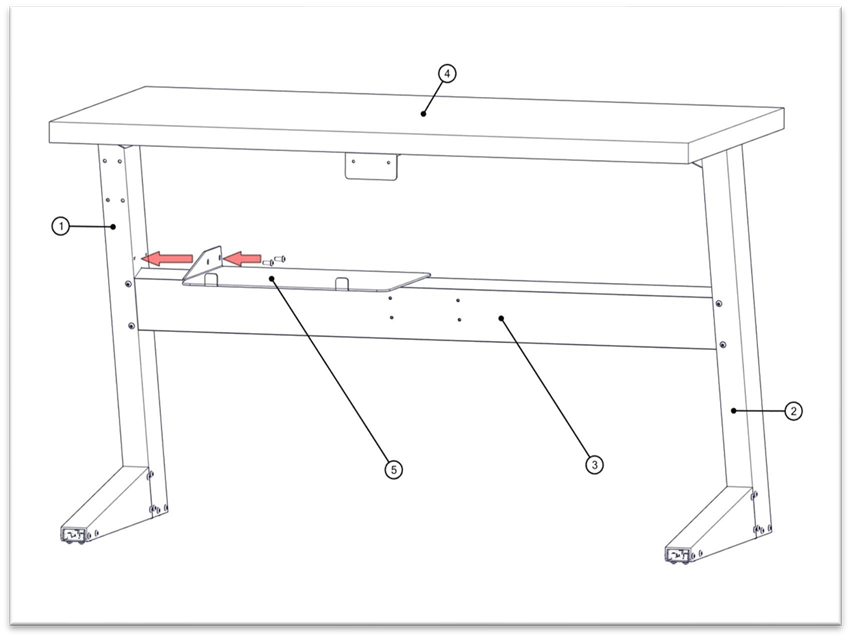
Connecting computer tray with the right leg
Step 5
Attach the Right and Left Side Mounting Brackets (Parts #7 and #8) for the Diagonal Column using two bolts per bracket. Ensure that the hook is facing upwards on both brackets.
Note: Do not fully tighten any bolts until every part is assembled.
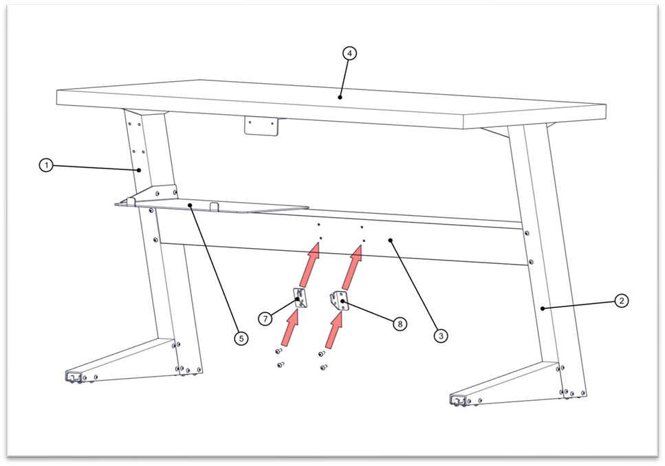
Attaching the right and left mounting brackets
Step 6
Attach the Diagonal Column (Part #6) to the Right and Left Side Mounting Brackets (Parts #7 and #8) using four bolts (two bolts on each side).
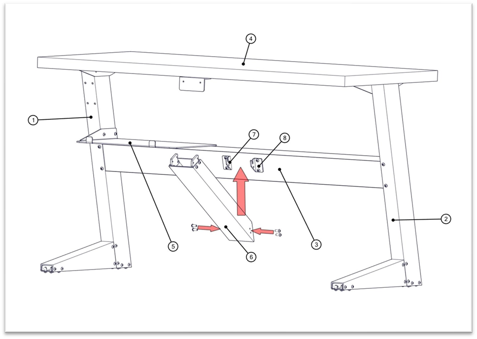
Attaching the diagonal column to the right and left mounting brackets
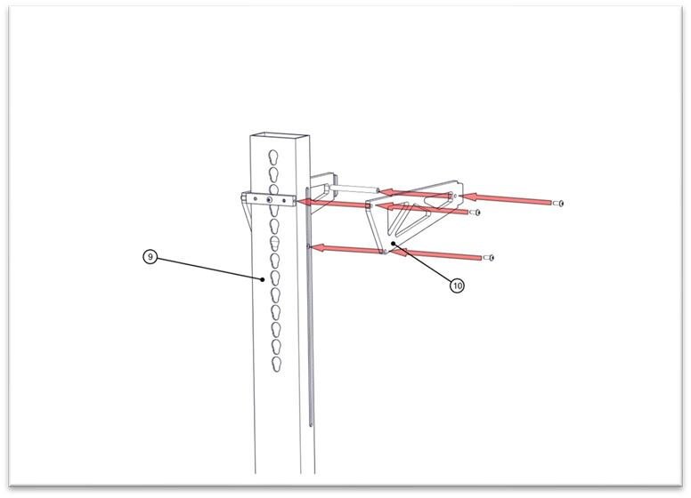
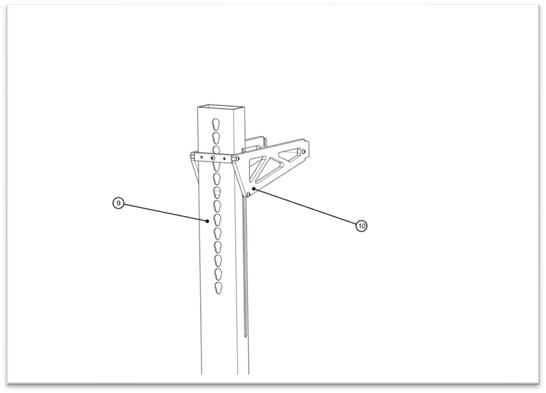
Step 7
Attach the Main Column (Part #9) on top of the Diagonal Column (Part #6) using four bolts (two bolts on each side). Also, attach the column to the table using two bolts from the rear cut out on the column.
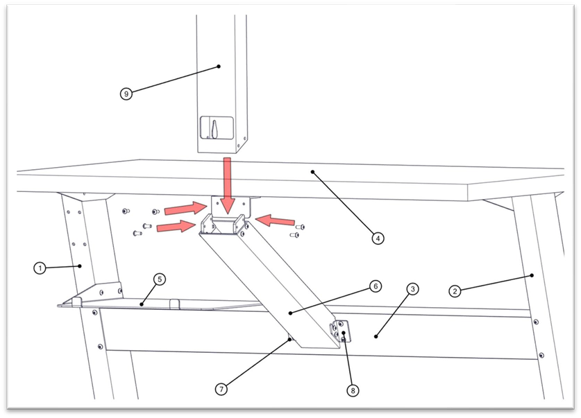
Attaching the main column(1)
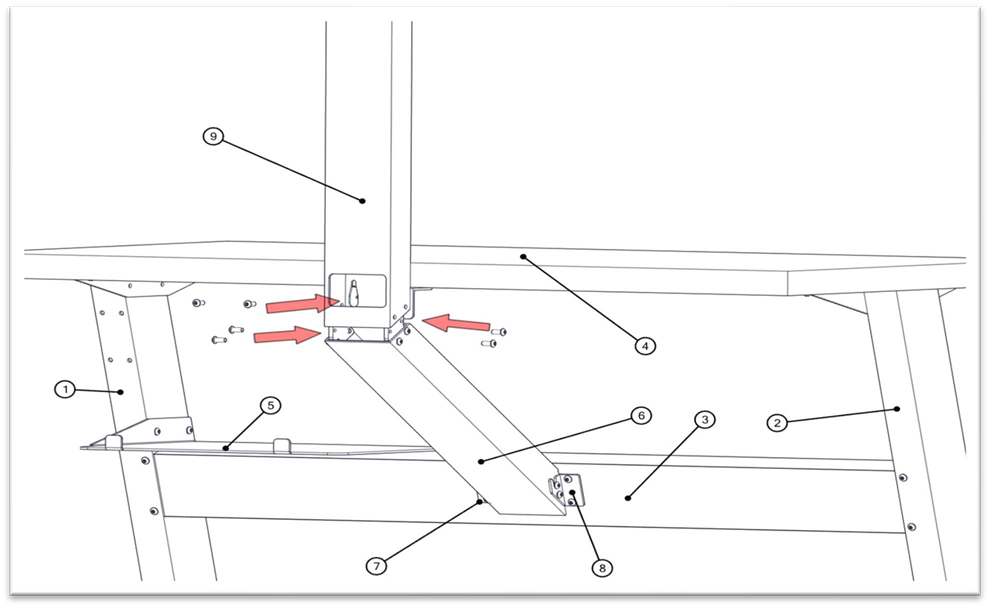
Attaching the main column(2)
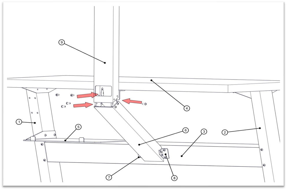
Attaching the main column(3)
Attaching the main column(4)
Step 8
Separate the Column Head (Part #10) as per the diagram below, by loosening the three bolts.
Separating the column head(1)
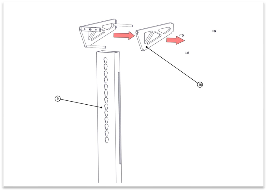
Separating the column head(2)
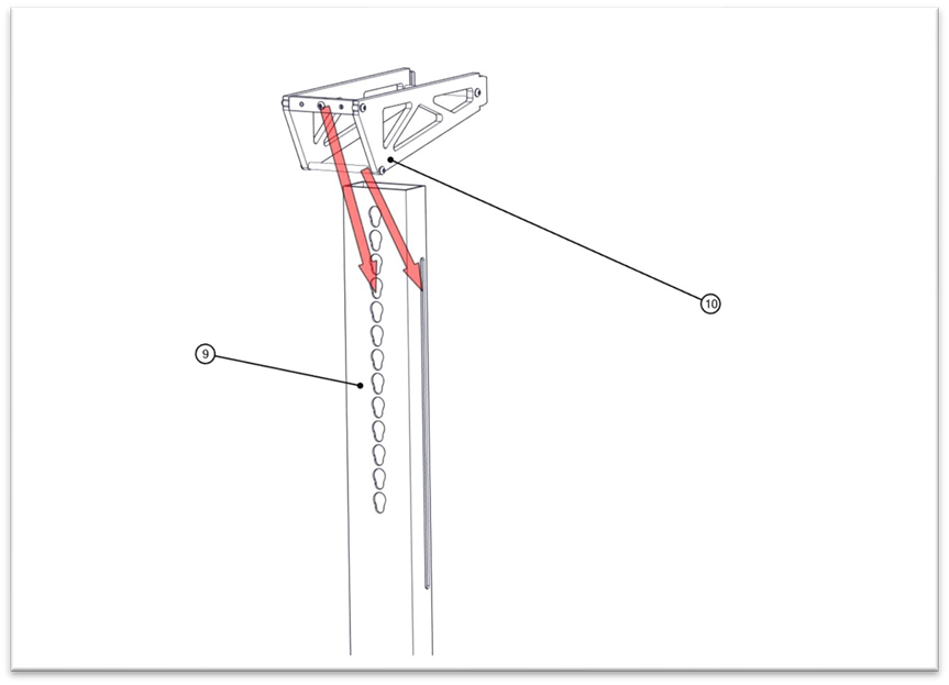
Step 9
Slide the right side of the Column Head (Part #10) into the Main Column (Part #9).
Sliding column head into the main column
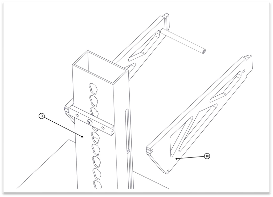
Step 10
Next, re-attach the left side of the Column Head to the right side of the Column Head using three bolts. The Column head will be held in position by an aluminum knob positioned on the rear. This knob will anchor into the holes, on the rear of the Main Column (Part #9).
Note: Do not fully tighten any bolts until the Light/Camera Fixture is attached to the Column Head (Part #10)
Re-attaching the column head(1)
Re-attaching the column head(2)
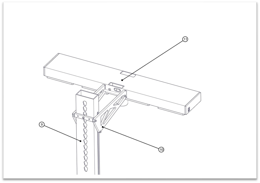
Step 11
Attach the Light/Camera Fixture (Part #11) to the Column Head (Part #9) by sliding the tabs from the Column Head into the Light/Camera Fixture. Now tighten the bolts on the Column Head. This will lock the Light/Camera Fixture to the Column Head as one piece.
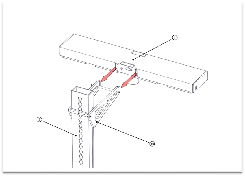
Attaching the light/camera fixture(1)
Attaching the light/camera fixture(2)
Step 12
Place the Tray Support (Part #12) on top of the table.
This piece is not bolted to the table. It is used as a guide for the trays to be counted. The user needs to position this manually for different types of trays. The rod on the Tray Support also needs to be relocated depending on the size of the trays.
Placing the support tray(1)
Placing the support tray(2)
Placing the support tray(3)
Step 13
Connect the Monitor Arm to the right side of the Right Leg (Part #1).
Note: Follow instructions with Monitor Arm assembly guide.
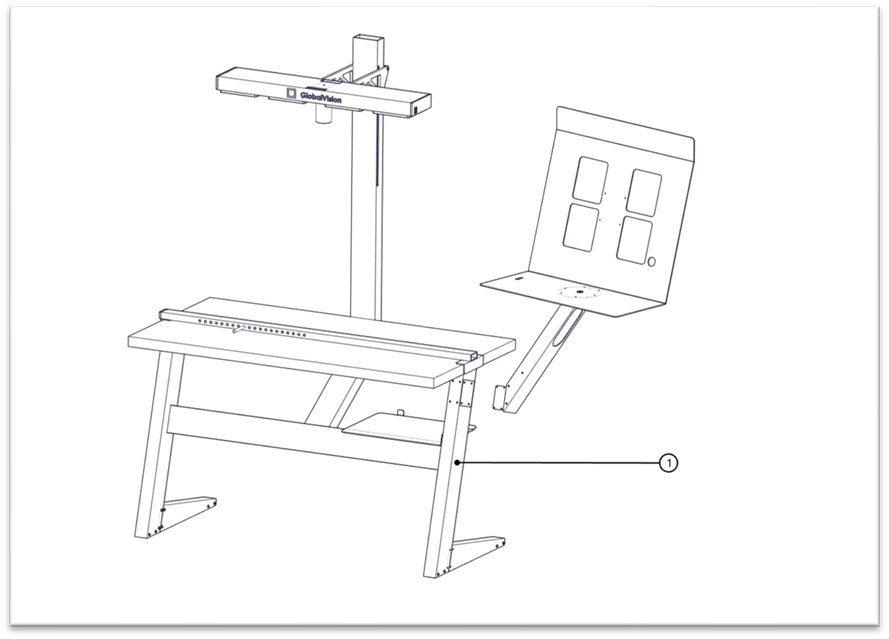
Connecting the monitor arm with the right leg(1)
Connecting the monitor arm with the right leg(2)
Step 14
Tighten all the bolts to ensure the Flatbed Scanner Table is safe and ready to use.
Assembly Guide PDF:
GlobalVision I-Count Assembly Guide rev.002.pdf