5.9.0 - Graphics Inspection - Pre Inspection Tools
Summary
This section describes the Pre-inspection tools needed to inspect any file before running a graphics inspection.
Pre-Inspection Tools Master and Sample Panel
Lasso Selection

Lasso Selection allows users to outline and select specific portions of the Master file which can either be included or excluded during a graphics inspection (shapes).
In order to add a portion of the Master to be inspected, using the Lasso Selection tool:
Click the Lasso Selection icon to access the drop-down option. Select Add to inspection.
Click on any point on the Master for the red dot to appear. This denotes the starting point. Now, drag and click and repeat again until you form the first segment. Once a segment is completed a yellow dot appears.
Note: To undo the last segment, click on the yellow dot and re-drag the segment.
Repeat this process until the last line connects to the very first point and the shape contains the portion of the Master which can be now included in the inspection. Add, any additional separate portions of the Master in the same inspection (if required). The inspection when run, will only verify the selected shape(s).
Note: Red Dot to Signify Created Point; Yellow Dot to Signify Created Segment that Can Be Undone.
In order to remove a portion of the Master to be inspected, using the Lasso Selection:
Click the Lasso Selection icon to access the drop-down option. Select Remove from inspection.
Click on any point on the Master for the red dot to appear. This denotes the starting point. Now, drag and click and repeat again until you form the first segment. Once a segment is completed a yellow dot appears.
Note: To undo the last segment, click on the yellow dot and re-drag the segment.
Repeat this process until the last line connects to the very first point and the shape contains the portion of the Master which can be now excluded from the inspection. Add, any additional separate portions of the Master in the same inspection (if required). The inspection when run, will only verify the selected shape(s).
Note: If a separate shape has been selected (i.e., a dieline) via Region Mode or the PDF Viewer and the lasso-selected shape(s) appear within, the dieline and all of its contents, excluding any portions that have been lasso-selected, will be inspected.
In order to remove Lasso Selection:
Right-click on the created shape. Select Reset to full page from the "Context" menu that launches.
Re-select the die line if necessary.
Region Mode

Region Mode lets you select an area in the image to be inspected.
Note: The minimum cropping area is 100 x 100 pixels.
In order to select an area in the Master image to be used in the inspection:
Click Region Mode and select one of the options:
Full Page: The entire page gets selected as the inspection area.
Shape: Shape mode is used to detect a shape for repeat detection. Left-click on the shape to be used as the inspection area. The selected shape displays in the Master panel.
Marquee: Left click and use the crosshairs to create the area to be inspected. A red box will appear surrounding the selected area.
Trim: The largest bounding area of the image is selected. A red box will appear surrounding the selected area.
Note: You can also create a shape for repeat detection with the Marquee tool, by creating the shape and clicking Crop to Contents afterward.
If you right-click on a layer (e.g. dieline) and choose Set as shape region & hide or Use as shape region in the integrated PDF Viewer, it automatically gets set as the Shape. Selecting the shape is key when inspecting repeats.
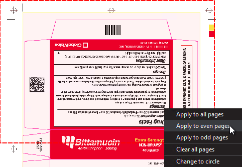
For marquee and trim selections, additional options exist in the "Context" menu that appears by right-clicking:
Choose between applying the selection to all, even, or odd pages in a multi-page file.
Click Change to circle to replace the rectangular selection with a circular one.
Click Clear all pages to remove the selection.
Crop to Contents

To tighten the crop selection so that it includes only the object:
Click Region Mode and select Marquee. Select an area using the crosshairs by click and drag. A red box will appear surrounding the selected area.
Click Crop to Contents.
Note: The crop selection adjusts so that it contains only the revised selection.
Color Picker
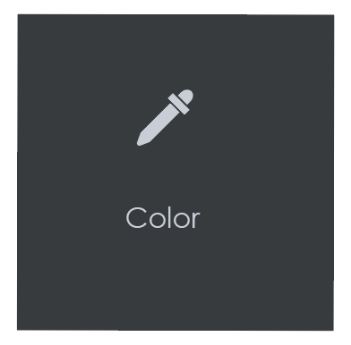
To display the RGB, CMYK, and LAB color-space information for a selected area in the Master image:
Click the Color Picker.
Click an area in the image. The Color Picker window displays the LAB, CMYK, and RGB color-space values of the point selected.
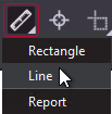
Measurement Tools
The Measurement Tools icon gives users access to both Rectangle and Line options when running a graphics inspection. By clicking and dragging the mouse on the file after making a selection, the user draws either a rectangle or line, with units displayed in either inches, millimeters, or pixels. This allows user to measure the size of graphic elements in the loaded file.
To measure a Line:
Click the Measurement Tools icon and select Line.
Click and drag the mouse on the file in the Sample panel in the desired location. Resize it by clicking on either one of its ends and then dragging.
Move the line by clicking on any other portion of the figure and then dragging.
When the cursor appears as a hand, you can move the line outright.
When the cursor appears as a vertical double-sided arrow, you can shift its angle.
Right-click for the option to delete the line.
To measure a Rectangle:
Click the Measurement Tools icon and select Rectangle.
Click and drag the mouse on the file in the Sample panel in the desired location. Resize it by clicking on its borders and then dragging.
Move the rectangle by clicking on its borders and then dragging. Right-click to either delete the rectangle or select Snap to the line for a closer crop.
To generate a PDF report of the measurements (without inspecting the files):
Click the Measurement Tools icon and select Report. When the Report Options window launches, fill in the fields as required.
Note: The PDF Attachment option is not available for Measurement Tools reports.
Click View or Save to generate the report, which lists each of the measurements made in inches, millimeters, and pixels.
Crop Sample
To select an area of the Sample image to be inspected:
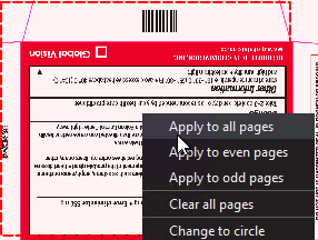
Click Crop. Left-click and select an area using the crosshairs that appear. A red dotted line surrounds the selected area.
Note: The minimum cropping area is 100 X 100 pixels.
Additional options exist in the "Context" menu that appears by right-clicking:
Choose between applying the selection to all, even, or odd pages in a multi-page file.
Click Change to circle to replace the rectangular selection with a circular one.
Click Clear all pages to remove the selection.
Support Rotated Repeats
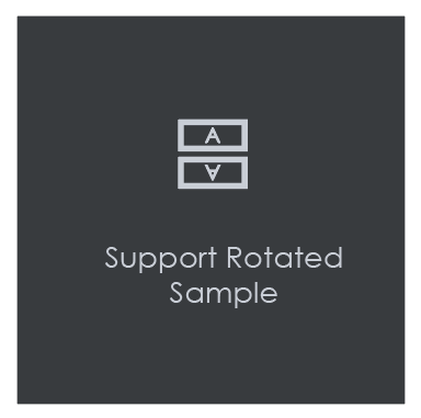
To run an inspection using a sample image that contains rotated repeats of the Master:
Click Support Rotated Repeats before running the inspection. During the inspection, the images are compared without considering rotation.
Note: Enabling this option will increase Inspection time significantly.
Match scale
Match Scale lets you compare images with different sizes by scaling the dimensions of the Sample’s cropped area to match the dimensions of the Master’s cropped area.
To use Match Scale:
In the Master panel, click Marquee and select the desired area
In the Sample panel, click Crop and select the other crop area.
Click Match Scale. When the inspection is run, the Sample cropped area is inspected as if it were the same size as the Master cropped area.
Note: Both the Master and Sample images must be cropped before Match Scale is used.